Thursday, November 09, 2006
Ray Intersection with A Torus: Root Finder
Okay, so a torus expands into an incredible quartic (polynomial of degree 4) equation to solve for t. So in other words you need a root solver. Now there are many times, there are some iterative approaches and then there are formulas for quadrics, cubics, quartics. So here is the java source for root finders of quadrics, cubics, quartis:
Source RootFinder.java
This code is distributed under the GNU GPL
Source RootFinder.java
This code is distributed under the GNU GPL
Tuesday, October 31, 2006
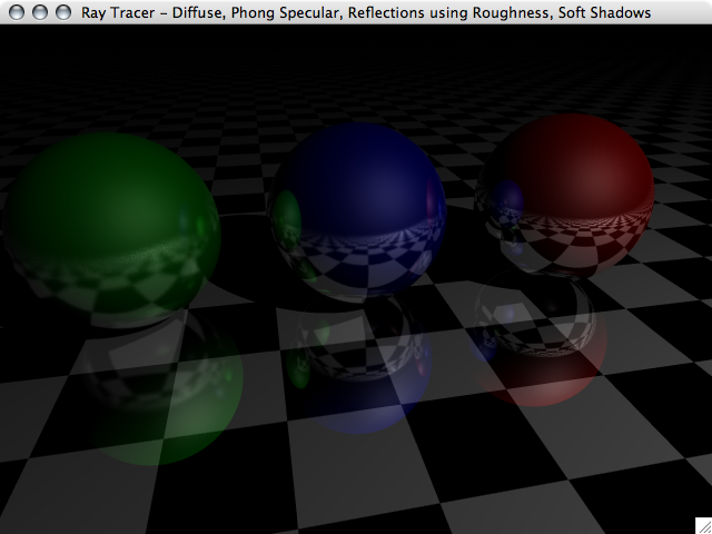
Reflections: So Smooth, Yet So Rough
So far our reflections only work on surfaces made of materials that are perfectly smooth. In the real world not all surfaces are pefectly smooth yet are still reflective. So to simulat this for doing refletions we cast multiple rays out from the reflection point to caclulate the direction they are cast we take the normal of the surface at the hitpoint and purterb it using a random gaussian variable. The roughness/smoothness is the standard deviation of the gaussian distribution used for perturbing the normals. So the larger the standard deviation the rougher the surface appears. So here's an example image.

Now lets enable the adaptive super-sampling with a circular sampling area and take a look at both the render and the frequency map of the rays per pixel. And we will lighten up the image a bit by adding another light.
Now lets enable the adaptive super-sampling with a circular sampling area and take a look at both the render and the frequency map of the rays per pixel. And we will lighten up the image a bit by adding another light.
 |  |
Adaptive Super-Sampling: More Rays Where We Need Them
A few posts ago I added super-sampling to the ray tracer to help take care of jaggies. If you remember, this consisted of sending more rays into the scene. There is a cost of sending in all of these added rays. Thinking back on the picture of the circle and the super-imposed grid we really only needed to fix the edges, the center of the circle didn't change at all. So we really wouldn't need to do anything to fix the non-existant jaggies in the center of the circle. So, in order to save on processing by not tracing any more rays than we absolutely have to while still looking good. In order to do this I wrote an adaptive super-sampling algorithem, well actually two of them. They both work off of the same idea that we've traced enough rays when tracing one more ray affects the average of all previously traced ray by only a very small amount.
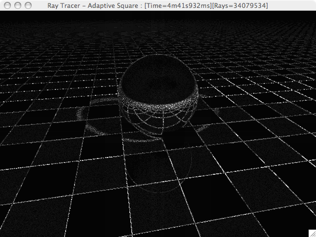
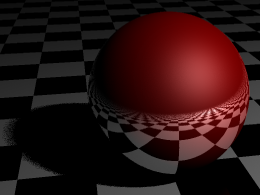
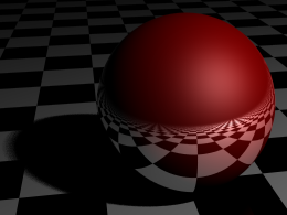
The first technique I wrote used a circular sampling area. The first step was to cast 8 rays around the perimeter of a circle centered at the current pixel. If the color of the center pixel was more than some epsilon from the average of the pixels on the radius we start casting more rays. We cast a random ray from withen the area of the circle and we keep casting until the difference between the current average and the average containing on more ray is less than epsilon. The left image is the normal render, the right one shows the number of rays cast for each pixel, the whiter the pixel the more rays cast. This graphically shows the adaptive aspect of the algorithem. You can see how along the edges more rays are cast than in the middle of square all the same color.
The second technique uses squares instead of circles, it starts by casting a ray for each point on a 2x2 grid and compares that average to the color at the center pixel, if the diffreence between them is greater than epsilon we increase the width of the square to 3, making it a 3x3 grid, compare that average to the grid before, if the difference is greator than epsilon keep repeating till is falls below epsilon.
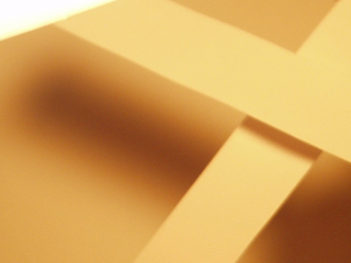
If we increase epsilon to 1x10⁻⁷, for the previous images it was at 1x10⁻⁵, we can see a drastic improvment in the shadow edges.
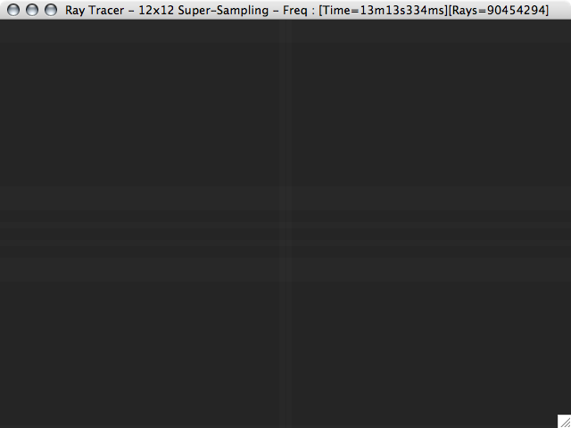
An interesting thing to note, if you click on the image it shows you the full size image and on the title bar are some statistics about the render, including time and number of rays cast. Notice that for this image of the the sphere about 41.7 million rays were needed on an 640x480 (307,200 pixels) image. That is about 136 rays per pixel. To get this same rays per pixel ratio without an adpative algorithem would use about a 12x12 square grid. Here is an image using a non-adaptive supersampling algorithem with a 12x12 grid, compare this to the previous image.
The first technique I wrote used a circular sampling area. The first step was to cast 8 rays around the perimeter of a circle centered at the current pixel. If the color of the center pixel was more than some epsilon from the average of the pixels on the radius we start casting more rays. We cast a random ray from withen the area of the circle and we keep casting until the difference between the current average and the average containing on more ray is less than epsilon. The left image is the normal render, the right one shows the number of rays cast for each pixel, the whiter the pixel the more rays cast. This graphically shows the adaptive aspect of the algorithem. You can see how along the edges more rays are cast than in the middle of square all the same color.
 |  |
The second technique uses squares instead of circles, it starts by casting a ray for each point on a 2x2 grid and compares that average to the color at the center pixel, if the diffreence between them is greater than epsilon we increase the width of the square to 3, making it a 3x3 grid, compare that average to the grid before, if the difference is greator than epsilon keep repeating till is falls below epsilon.
 |  |
If we increase epsilon to 1x10⁻⁷, for the previous images it was at 1x10⁻⁵, we can see a drastic improvment in the shadow edges.
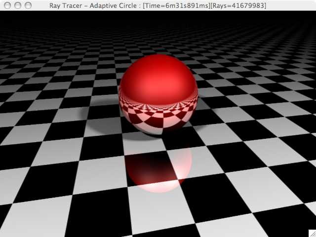 | 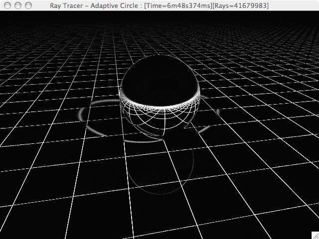 |
An interesting thing to note, if you click on the image it shows you the full size image and on the title bar are some statistics about the render, including time and number of rays cast. Notice that for this image of the the sphere about 41.7 million rays were needed on an 640x480 (307,200 pixels) image. That is about 136 rays per pixel. To get this same rays per pixel ratio without an adpative algorithem would use about a 12x12 square grid. Here is an image using a non-adaptive supersampling algorithem with a 12x12 grid, compare this to the previous image.
 |  |
Monday, October 30, 2006
Soft Shadows: Area Lights
Up to now the lights have only been represented by a single, infinitesimally smally point. This doesn't accurately model light in the real world which comes from an object have volume. Look at a light bulb, it takes up some amount of space. The side affect of have a point light is that all the shadows are really sharp, they have very defined edges. While the edges of shadows cast by lights with volume or area have soft edges. Here is a picture of the soft edges cast in real life:
(Image courtesy of Shadow Rendering Home Page at Lund University @ http://graphics.cs.lth.se/research/shadows/real_soft_overlap2.jpg)
Here is a series of images using area lights:

Here is a series of images using area lights:
 |  |  |
Saturday, October 28, 2006
Reflections: Images of Mine Self
So far all of our objects are dull and flat, we could easily make this more cool by adding in reflections. The technique is simle, we cast the ray from the eye, hit the object, and then cast another ray reflected off the object. This creates nice reflective objects, the first one only allows things to reflect once.

With only one reflection we can't get the hall of mirrors effect. In order for things to reflect of themselves in their reflections we need to increase the depth we will trace reflections. To see what I mean, notice in the image above, the blue spehre is refelected on the green sphere. In the following image, we can see the reflection of the green sphere on the blue sphere in the reflection of the blue sphere on the green sphere. We can really notice the double reflections in the right hand image which is a zoom-in on the red sphere of the left image.
In the image below we can see a class of problems in ray tracing called acne problems. This particular one is a reflection acne. The acne is the odd looking lines all over the image. Some cases look more like acne, lighting acne shows up as block dots all over the objects. The acne comes from the fact that computers can only represent finite numbers. There is only so much information that can be used to represent a number, in this case 64-bits. This finite space means that we can only represent a finite amount of numbers. The side affect of this is that when we are doing intermediary calculations we can lose some of the number before getting to the final answer. Well, if we calculate the same number but reorder the operations we might get a slightly different answers. E.g. D * (A + B + C) is not guarenteed to equal D * A + D * B + D * C, especially if D is very large comparred to A, B, or C.


With only one reflection we can't get the hall of mirrors effect. In order for things to reflect of themselves in their reflections we need to increase the depth we will trace reflections. To see what I mean, notice in the image above, the blue spehre is refelected on the green sphere. In the following image, we can see the reflection of the green sphere on the blue sphere in the reflection of the blue sphere on the green sphere. We can really notice the double reflections in the right hand image which is a zoom-in on the red sphere of the left image.
 |

In the image below we can see a class of problems in ray tracing called acne problems. This particular one is a reflection acne. The acne is the odd looking lines all over the image. Some cases look more like acne, lighting acne shows up as block dots all over the objects. The acne comes from the fact that computers can only represent finite numbers. There is only so much information that can be used to represent a number, in this case 64-bits. This finite space means that we can only represent a finite amount of numbers. The side affect of this is that when we are doing intermediary calculations we can lose some of the number before getting to the final answer. Well, if we calculate the same number but reorder the operations we might get a slightly different answers. E.g. D * (A + B + C) is not guarenteed to equal D * A + D * B + D * C, especially if D is very large comparred to A, B, or C.

Anti-aliasing: Kill Those Jaggies!
What are Jaggies
We have diffuse and specular lighting and shadows, things look pretty nice . . . except for those jaggies. What are jaggies you say? They are technically called aliasing, and it comes from the fact that computer sreens are made up out of pixels. Pixels have a size, while very small, they still have an area. Aliasing happens when say a line goes through they corner of a two pixels. Well a pixel has to turn all of itself on or none. It can't have half a pixel on. And this creates those jagged edges. Look here at this example. The left image has a smooth looking circle, then on the middle image I've overlayed a grid, imagine each square to be a pixel on the screen. Notice how some squares are only partially filled. Since we can't have only half the pixel glowing we must fill in the whole square. This produces the rough "jagged" image on the right. | 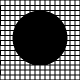 | 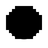 |
Show Me Some Real Life Jaggies
Now that you understand what they are, here are two images of our scene, the left one has very prominent jaggies, the right one has much less noticible ones. |
If we zoom in on the green sphere and on the floor we can really those jaggies. The far right image is the middle one enlarged by a factor of two.
 |  |  |
Let's Fix Them!
So how do we fix it? Its rather simple. In ray tracing we shoot a ray through each pixel of the image and remember that the whole pixel must glow so this creates jaggies. However, we can get rid of them by shooting a ray between pixels and averaging them up to find the final value for a single pixel. This technique of sending in more rays is called super-sampling So for the following images instead of one ray per pixel, nine rays were cast, a three by three grid.These images are of the same regions as the previos there. |  |  |
Shadows
So far so good, things are looking pretty spiffy. But there is still something lacking as far as lighting goes. Any ideas? There are no shadows! This must be fixed, we mush have shadows. So how do we do shadows? We cast a ray into the scene, it hits an object and from that hit point we cast another ray to all the lights in a scene. So for shadows we just add one more step, when we cast a ray from the hit point to all the lights in the scene we check to see if anything is between the hit point and the light. The blocked path from hit point to light is what causes shadows, since if we don't have a clear path to the light it doesn't contribute to the lighting of that hit point. Now that we have shadows this is what things look like:
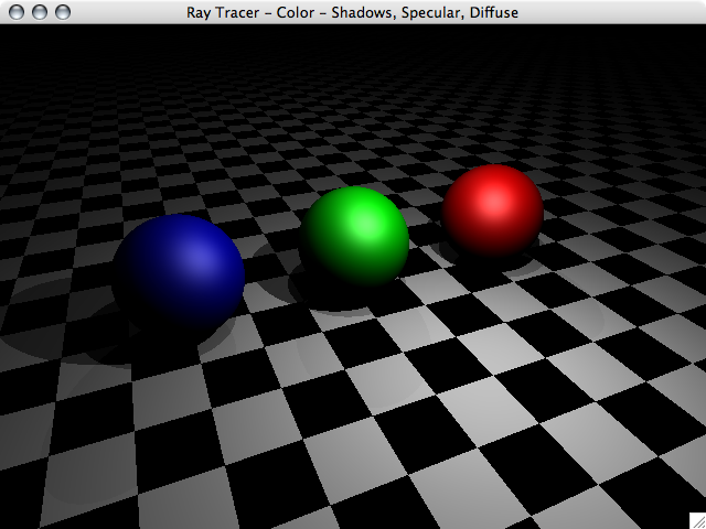
Specular Lighting
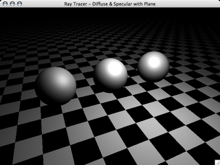
Well, we have diffuse lighting wich handles matte surfaces and such, but to get the highlights that lighting can create we need to add what is called specular lighting. There are several techniques for doing specular lighting. First I will just be using what is called Phong shadding as its easier to implement, then later in the project, I will move on to Cook-Torrance shading which is more realistic. So here is an image of our scene with Phong specular shading.
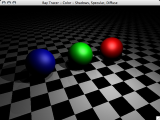
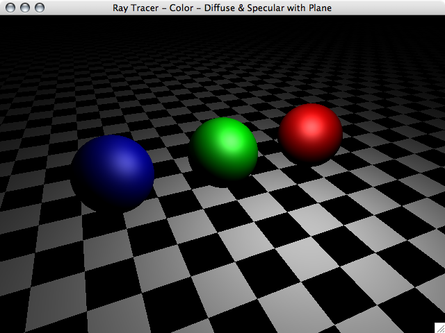
It's looking pretty good, but rather drab, time for some colors. How about Red, Green, and Blue, a computer scientists favorite colors. So here are our now colored spehrers complete with diffuse and specular lighting.

It's looking pretty good, but rather drab, time for some colors. How about Red, Green, and Blue, a computer scientists favorite colors. So here are our now colored spehrers complete with diffuse and specular lighting.
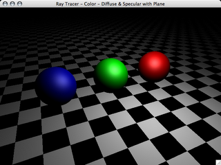
Diffuse Lighting
Well, with the hit test now working, its time to move on to diffuse lighting. This is pretty simple todo, go check Wikipedia to find out how. This isn't a walkthrough of putting together a ray-tracer.
The next step is to add specular lighting.
Diffuse lighting on our three spheres: 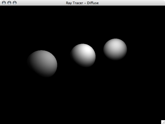 | A plane added to our scene. 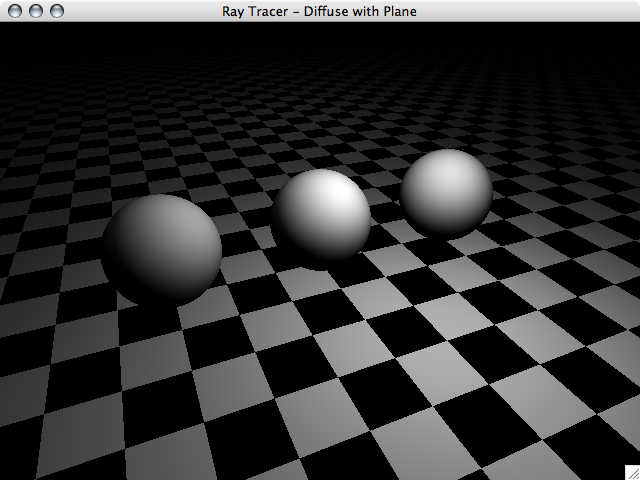 |
The next step is to add specular lighting.
Friday, October 27, 2006
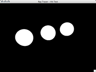
Hit Test
The first step is drawing a simple hit test. In other words, no lighting, no reflections, no fancy stuff. Just draw pure white if found an object and complete black if there is nothing there. Here is a screen shot of the hit test:

The Project
As the final assigned project for my Computer Graphics class at SNU we have to write a ray tracer. Being the over acheiver I am, I already have what will probably be 80% of the project finished, before it is even assigned. So, I will be blogging on the progress of the project as I write. See as I've already done a fair bit, these first posts will be of the work I did in the past couple of days and finish with what I currently have.
![]()